Parker JM Clipper® Seals - Engineering Recommendations

Shaft Recommendations

Materials - Parker recommends a shaft material of carbon steel with a minimum hardness of Rockwell C30 (30 Rc). Soft materials such as bronze, aluminum or plastic should be avoided because they are susceptible to grooving and will cause premature seal failure. If a soft shaft material must be used, a Parker Quick Sleeve or Parker Wear Sleeve can be installed over the soft shaft material to provide a durable sealing surface.

Shaft Finish - Parker recommends a plunge ground finish of 8 to 17 μin Ra (0.20 to 0.43 μm Ra) with zero lead. A shaft finish significantly smoother or rougher will shorten the service life of the seal.

Shaft Profile - The shaft profile should include a lead-in chamfer per the following example. The leading edge helps prevent lip roll-back and spring dumping. The leading edge and trailing edges should be free of burrs or sharp edges that could cut the contact point of the seal lip.

Clipper Chamfer Diagram
English Shaft Dia. - up to & Including Length "w" (inch) Metric Shaft Dia. - up to & including Length "w" (mm)
0.375 0.051 10 1.3
0.750 0.068 20 2.0
1.250 0.085 30 2.2
1.500 0.102 40 2.6
2.000 0.119 50 3.0
2.750 0.136 70 3.5
3.750 0.153 95 3.9
5.000 0.188 130 4.8
9.000 0.239 240 6.1
+ 18.000 0.375 480 10.0

Shaft Tolerance - To ensure the proper lip-to-shaft interference is maintained, shaft diameters should fall within the tolerances specified. Shafts significantly over the tolerance will increase the underlip temperatures and lead to premature failure. An undersized shaft compromises the amount of lip interference available to maintain a positive seal.

Shaft Tolerance for Inch/Fractional

Shaft Diameter Tolerance
Up to 4.000" ± .003"
4.001 - 6.000" ± .004"
6.001 - 10.000" ± .005"
Over 10.000" ± .006"

Shaft Tolerance for Metric*

Shaft Diameter Tolerance
Up to 10 mm ± 0 to -.09 mm
Over 10 - 18 mm ± 0 to -.11 mm
Over 18 - 30 mm ± 0 to -.13 mm
Over 30 - 50 mm ± 0 to -.16 mm
Over 50 - 80 mm ± 0 to -.19 mm
Over 80 - 120 mm ± 0 to -.22 mm
Over 120 - 180 mm ± 0 to -.25 mm
Over 180 - 250 mm ± 0 to -.29 mm
Over 250 - 315 mm ± 0 to -.32 mm
Over 315 - 400 mm ± 0 to -.36 mm
Over 400 - 500 mm ± 0 to -.40 mm

Housing Recommendations

Material - The most commonly used materials for seal housings are steel and cast iron. Care must be taken when softer housing materials such as aluminum, bronze or plastic are used.

Housing Finish - A finish range of 40 to 100 μin Ra (1.0 to 2.5 μm Ra) is recommended. The Clipper seal is more tolerant of housing finishes that are toward the upper limit than metal OD seals.

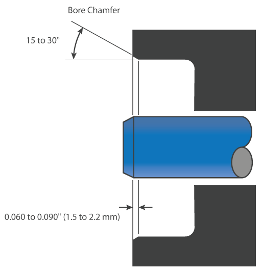
Housing Profile - A lead-in chamfer per the following example is highly recommended for all seal housings. The chamfer aligns the seal during installation and helps prevent the seal from cocking. Both corners of the chamfer should be free of burrs and sharp edges to eliminate OD damage during installation.

Clipper Housing

Housing Tolerance - The diametrical tolerance of the housing for Clipper Oil Seals should be within the limits.

Bore Diameter Diameter Tolerance H1 Diameter Tolerance STH1 Depth Tolerance (-0/+)
Up to 5.9" ± .002" ± .002" + .031"
6.0- 15.9" ± .005" ± .002" + .062"
16.0 - 30.9" ± .008" ± .005" + .062"
Over 31.0" ± .010" ± .005" + .062"
Bore Diameter Diameter Tolerance H1 Diameter Tolerance STH1 Depth Tolerance (-0/+)
Up to 150 mm ± .05 ± .05 + .8
151 - 403 mm ± .13 ± .05 + 1.5
404 - 785 mm ± .20 ± .13 + 1.5
Over 786 mm ± .25 ± .13 + 1.5