Video Transcript
Hello and welcome to another installment of “Not All O-Rings Are Created Equal.” I’m going to take a few minutes today to talk about one of the common failure modes of an o-ring and some of the factors that should be considered or be aware of to alleviate any such failures.
O-Ring Spiral Failure Examples
For example, did you know that in dynamic reciprocating applications an o-ring is not recommended for strokes of 12 inches or longer? A lot of applications out there, especially reciprocating that tend to stroke longer than the 12 inches. There’s a lot of factors that must be considered and we’ll talk about some of those as we go along.
As a rule, anything over 12 inches is not recommended.
In addition, in dynamic reciprocating applications, the direction of pressure and the seal friction should oppose each other.
Failure will likely occur if pressure and friction both are of the same direction.
What Is O-Ring Spiral Failure?
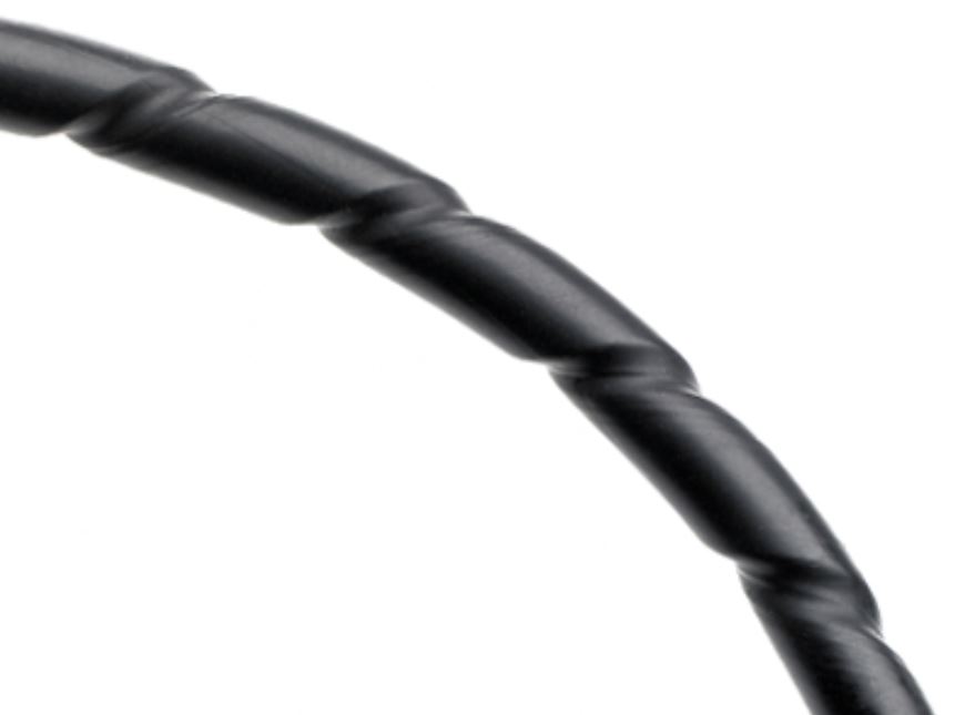
Now, these are just two examples of a common failure that is given the term spiral failure. I want to talk a little bit more about spiral failure and an understanding of what that is. According to the Parker o-ring handbook, which is his kind of the Bible to the o-ring industry, this type of failure was given the name because when it occurs, the seal looks like it’s been cut halfway through the o-ring.
The cross-section of the o-ring actually has a corkscrew or spiral look to it. An o-ring usually seals in that condition until you get a complete break, but it does cause fatigue and it doesn’t lend itself to susceptibility to breaking once it has spiraled.
The Sliding Effect
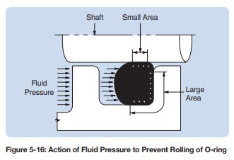
Having said that, a properly used o-ring slides during the reciprocating stroke. There’s actually movement of the o-ring. The hydraulic pressure produces a greater holding force within the groove that produces the sliding effect. If it doesn’t slide, it is going to roll. The smoother finish of the sliding surface in relation to the groove surface finish produces less friction. Stands to reason. Running friction is lower than breakout friction. The torsional resistance of the o-ring also resists twisting. The compound, the material, as we discussed in other sessions, what are the differences in o-ring materials themselves?
Not Just O-Rings
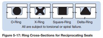
I want to talk a little more about the torsional, or spiral failure, and the fact that it is not limited to just an o-ring cross section.
There are many applications where you’ll use what they call a X-Ring, a square section or a lathe cut, an x-ring – these types of seals are also susceptible to spiral failure given those same conditions. I’m not going to go into a lot of detail in all of those but there’s actually quite a list of things that need to be factored into the design when applying o-rings in reciprocating applications to reduce or eliminate spiral failure:
- The speed of the stroke itself
- The media that is being used, or the lack of lubrication
- We talked about the pressure differential
- Squeeze – if you have too much
- What’s the shape of the grooves or are the grooves split?
- The length of stroke
- Surface finish
- The type of metal that is being used
- Is there a side load? Is it absolutely concentric all the way around?
- And there are several others
These are all factors that can a tribute to spiral failure which can be a catastrophic failure in o-rings. To learn more about it, go to the ESP International website to find the Parker O-Ring handbook. It’ll give you much greater detail to how to avoid spiral failure in application.