Click on the image to open in a New Tab.
Video Transcript
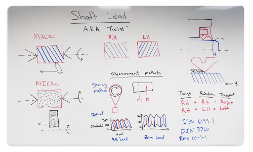
Shaft lead also known as twist. Shaft lead, if not well understood and defined on your specifications, can have a detrimental impact to the performance of a dynamic sealing system.
Typical rotary applications have an elastomeric sealing element interfacing with a rotating shaft. On the shaft surface, the characteristics are very important and critical to the proper operation of the sealing system. One of those characteristics is shaft lead.
Macro Shaft Lead
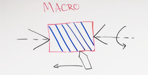
A typical manufacturing process may be the use of a single point tool against a rotating shaft where the tools actually traversing the surface of the shaft. This operation will result in a spiraling groove pattern around the circumference of the shaft. In this type of pattern, we refer to it as macro lead – has a continuous thread-like structure.
Micro Shaft Lead
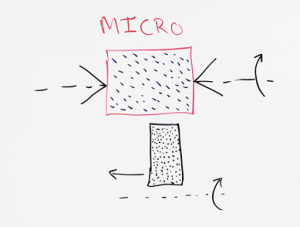
An alternative process maybe traverse grinding.
In this case, we don’t have a single point tool rather a stone with multiple points that contact the rotating shaft. The stone is still traversing along the surface of the shaft and it does result in micro lead. The threadlike structures are not continuous, but they do have a deviation from the circumferential direction of the surface of the shaft resulting in shaft lead.
Two Orientations of Shaft Lead
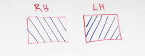
Shaft lead can have two orientations. It can be a right-hand orientation. Where it’s shown here on the moving from the bottom right to the top left corner of the image and left-hand lead where you’re actually the threadlike pattern is from the bottom left to the top right.
Results In A Sealing System
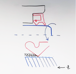
So what does this do in a sealing system?
Again, in a rotary sealing system, we have an elastomeric sealing element that is interfacing with a rotating shaft.
If we look closer at the surface of the shaft and in this illustration, I actually have drawn a right-hand lead type structure. We can see where the oil is in contact with the shaft surface and the sealing lip.
As the shaft rotates depending on the direction of rotation, it will actually transport oil from left to right or right to left. Because this is right-hand twist if we have a right-hand rotation – so the top of the shaft moving towards the bore – we will actually end up with movement of the oil from left to right. So in this case out of the sealed system resulting in leakage.
If we have left-hand rotation, so in this case, the top of the shaft moving out away from the bore you will result in movement from right to left. So left-hand transport. This will help retain the oil in the system.
However, if it’s aggressive enough transportation of the oil it will actually result in a lack of proper lubrication at the interface between the sealing lip and the shaft surface could lead to premature wear of the sealing lip.
Twist, Rotation, Transport
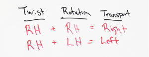
So again right-hand twist right-hand rotation – the transport is to the right. A right-hand twist with a left-hand rotation – the transportation is to the left.
String Method & Optical Method
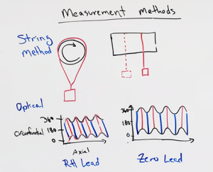
So how can we measure and hopefully quantify shaft lead on an actual physical component? There are two major categories out there. There are a lot of different methods developed over the years, but the oldest and most well-known method is referred to as the string method or the thread method.
In this method, you mount a shaft in a rotating device. You drape a thread with a weight attached to it over the shaft. From the side view as you slowly rotate the shaft you may observe movement to the left or to the right from its original position.
If you do observe movement, you are observing that the shaft likely has lead. You cannot easily and precisely quantify accurately the amount of lead that exists in the shaft, but you can get a qualitative sense of whether or not you have left-hand or right-hand shaft lead.
A more precise and accurate method of measurement is using an optical method. In an optical method, you are creating a 3D mapping or 3D profiling of the entire surface of the shaft.
Software can then collect the data and process it to produce a representation of the effective shaft lead of the system.
The image on the left you can see as you move in the circumferential direction from 0 to 360 Degrees. You actually have axial movement along the shaft. In the one on the right-hand side you can see as you move from 0 to 360 Degrees, you actually have zero movement along the axial position of the shaft. This one we would refer to as having right hand lead this one having zero lead.
Using the optical methods, you can get a precise and accurate quantification of the lead angle, which can be useful when you are inspecting or qualifying components for a new product.
Industry Specifications

Some of the specifications that exist and are used in the industry that you may see include ISO 6194 – 1 and DIN 3760. Both of which specify zero lead. RMA OS-1-1 actually does tolerate lead to a very small level.
There are other specifications out there. There are also specifications that exist for most major OEMs where they have expanded on the information that’s available in the industry standard specifications.
Conclusion
The main thing to remember is that if you are not aware of what your tolerances for shaft lead in your sealing system, or you’re not aware of what your actual lead is, you could end up with performance issues that are not easy to identify the root cause.
And in many cases we find that in a situation where you’re not able to identify the root cause of a sealing system failure in a rotating system – if it’s not a tribute attributable to the elastomeric seal or to other obvious installation design issues – in some cases it’s actually result of the presence of lead that is hard to detect and again not very well understood.