Seth Chunn, Application Engineer at ESP International
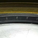
Figure 1: An example of what spline damage can look like on an elastomer seal.
Seals play a critical role in applications, whether they are excluding contaminant or sealing in a fluid. The purpose of this article is to provide general guidelines for what may cause leakage or failure of an elastomeric radial shaft seal based on visual inspection of the failed seal.
The path to a diagnosis starts with removing the seal from the housing and analyzing the characteristics of the lip. When removing the seal, it is important to minimize the deformation and damage to the seal. Removal damage can mask the evidence of why the seal failed, and as a result extends the timeline to finding a solution. This article will discuss three examples of failure mode characteristics:
- Spline Damage
- Heat Cracking
- Track Width
Spline Damage
Splines are a common feature in systems where radial shaft seals are required, as well as common causes of seal damage during seal installation. Seals and splines are often installed using a method where they pass through, or over, each other. If a spline diameter meets or exceeds the shaft diameter of the seal, there is a risk of damage to the primary sealing lip. Figure 1 illustrates an example of what this damage could look like on a seal. The visible markings were left behind by splines scratching the seal surface, resulting in a leak path which can cause oil leakage during operation. Some recommended methods to avoid spline damage include designing the splines to have a smaller diameter than the seal lip or using an installation cone to cover the splines.
Heat Cracking
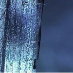
Figure 2: Heat cracking on a seal lip.
Seals are also susceptible to failure through heat cracking. Heat cracking on a seal lip is the result of the elastomer being exposed to temperatures above its capability. Examples of contributing factors to the temperature beneath the seal lip are internal pressure, oil temperature, and speed. Based on speed alone, the temperature beneath the seal lip can exceed the sump oil temperature by up to 20 degrees Fahrenheit. This difference results from the friction between the seal and the mating shaft. When a seal lip suffers heat damage, it becomes brittle as the carbon in the polymer breaks down. This allows cracks to form and begin to propagate across the lip, as seen in Figure 2. This process destroys the elastic properties of the lip and creates a leak. If leakage occurs, the seal lip should be analyzed for cracks and flexed while listening for a cracking sound. If either of these signs is seen or heard, it is likely that the seal suffered from heat damage. Should a seal be suspected of experiencing heat damage, it is imperative to review the application and determine possible causes for the unexpected under-lip temperatures.
Track Width
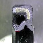
Figure 3: A large track width highlighted in red on a seal.
Another failure mode characteristic is a large track width. Throughout a seal’s lifetime, the original sharp lip will slowly wear and start to resemble a flat surface. This flat surface is referred to as a track width. The rate of wear is a function of many inputs, ranging from material compounding to prolonged service hours. Time is an important factor when considering the extent of seal wear. If a seal demonstrates significant wear in a short amount of time, this is concerning. The definition of a “short amount” of time varies and is based on application and manufacturer expectation. In many instances, the cause for the undue wear on the seal lip is not clear. The only defense against seal wear, aside from material quality, is the thin layer of oil that is in dynamic equilibrium under the seal lip, called the hydrodynamic effect. The absence of this layer results in failed lubrication of the seal and is the most common cause of undue wear. Subsequently, this results in the formation of a large track width.
Surface finish, lead, and lubricant viscosity are a few factors that can create a lack of lubrication under the seal lip, which leads to a large track width. Elastomeric radial shaft seals require a balanced surface finish. If the surface is too rough, the seal lip will wear prematurely. If the surface is too smooth, the shaft will lack the necessary pockets for oil to reside and maintain lubrication. It is widely accepted that a Ra of 10-20 micro-inches is appropriate, but can vary between application and manufacturer. In addition to surface finish, shaft lead is a major concern on the mating shaft. Lead can mechanically pump oil away from the seal lip. The loss of oil results in direct contact between the seal and shaft, causing significant wear. Figure 3 shows a seal that experienced wear, causing a large track width. The damage pictured in Figure 3 occurred after a short amount of time and the formation of the large track width was determined to be a result of inadequate lubrication. In this case, the oil used exceeded the viscosity for this seal profile and prevented the formation of the thin oil film beneath the seal lip. Currently, there are no established guidelines connecting oil viscosity to seal profiles. However, in practice, it is possible to alter the surface finish to accommodate a chosen oil viscosity, but must be verified through experimentation.
Summary
The steps for analyzing a failed seal begin with a cautious removal process, followed by thorough visual analysis of the seal lip. The lip should be able to flex without damage and should exhibit typical wear patterns for the application. ESP International offers failure analysis for many OEM customers, as well as others. If you have any questions regarding any seal failures
Have a question?
Fill out our contact form or Call (319) 393-4310 and request to speak with the engineering departement.